The alternator system in a Honda vehicle consists of several components, including the alternator itself, the voltage regulator, the battery, and various wiring and connectors.
The wiring diagram for the 4 pin alternator connector provides information on the functions and connections of each wire, making it easier to diagnose and repair any issues with the alternator system.
By familiarizing yourself with the wiring diagram for your specific make, model, and year of Honda vehicle, you can ensure that your alternator is functioning correctly and keep your vehicle running smoothly.
Honda 4 Pin Alternator Connectors
In a Honda 4 pin alternator wiring diagram, there are two main connectors to be aware of: the B terminal on the alternator and the 4 pin connector.
The B terminal, also known as the battery terminal, is located on the back of the alternator. It is connected to the ground source and is responsible for providing power to the battery. The wire connected to the B terminal is typically white.
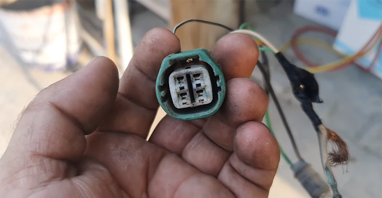
The 4 pin connector, also known as the alternator connector, is the main connection point between the alternator and the rest of the electrical system in the vehicle.
It typically consists of four wires, each with a specific function. The colors of the wires in the 4 pin connector can vary depending on the make, model, and year of the vehicle.
Honda 4 Pin Connector Wiring and The Diagram
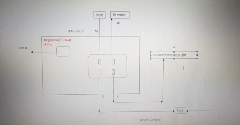
The 4 pin connector in a Honda 4 pin alternator wiring diagram is responsible for connecting the alternator to the rest of the electrical system in the vehicle. Each wire in the 4 pin connector serves a specific function.
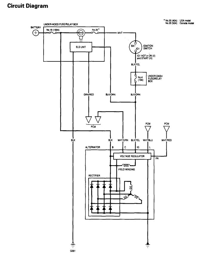
- The black/yellow wire is the 12v (+) power source, which provides power to the alternator and the battery.
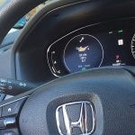
- The white/blue wire is connected to the ICU/Instrument Cluster (Battery Light), which is responsible for illuminating the battery light on the dashboard when the alternator is not functioning properly.
- The white/red wire is the FR signal to ECM (D9), this wire sends a signal to the Engine Control Module (ECM) indicating the alternator’s current output.
- The white/green wire is the ECU output signal (D10), this wire sends a signal from the Engine Control Module (ECM) to the alternator indicating the required alternator output.
| Connector | Terminal | Function | Color |
|---|---|---|---|
| B terminal | Battery | Ground | White |
| 4 pin connector | 1 | 12v (+) Power source | Black/Yellow |
| 4 pin connector | 2 | ICU/Instrument Cluster (Battery Light) | White/Blue |
| 4 pin connector | 3 | FR signal to ECM (D9) | White/Red |
| 4 pin connector | 4 | ECU output signal (D10) | White/Green |
Note: It is important to note that the colors of the wires in the 4 pin connector can vary depending on the make, model, and year of the vehicle. Therefore, it is important to consult the wiring diagram for your specific vehicle to ensure proper identification of the wires and their functions.
FAQ
A: The B terminal, also known as the battery terminal, is located on the back of the alternator. It is connected to the ground source and is responsible for providing power to the battery.
A: The black/yellow wire in the 4 pin connector is the 12v (+) power source, which provides power to the alternator and the battery.
A: The white/blue wire in the 4 pin connector is connected to the ICU/Instrument Cluster (Battery Light), which is responsible for illuminating the battery light on the dashboard when the alternator is not functioning properly.
A: The white/red wire in the 4 pin connector is the FR signal to ECM (D9), this wire sends a signal to the Engine Control Module (ECM) indicating the alternator’s current output.
A: The white/green wire in the 4 pin connector is the ECU output signal (D10), this wire sends a signal from the Engine Control Module (ECM) to the alternator indicating the required alternator output.
A: It is very important because the wiring diagram can vary depending on the make, model, and year of the vehicle.
Therefore, it is essential to consult the wiring diagram for your specific vehicle in order to ensure proper identification of the connectors, wires, and their functions.
A: You can find additional information in the vehicle’s service manual, technical forums, and local auto parts stores.
It is also recommended to consult a professional mechanic or technician for help with troubleshooting and repairing any issues with the alternator system in your vehicle.